CypCut and HypCut CNC machines, manufactured by Friendess/Bochu, are carving out an increasingly important niche in the laser cutting machine market. Their growing popularity is due to the fact that they are not tied to a specific manufacturer, as well as their great versatility and functionality.
For laser cutting, the cutting parameters are certainly fundamental. Setting the correct cutting tables is crucial for obtaining a high-quality cut, maximising the machine’s potential. No laser cutting machine, however skilfully manufactured, will ever work well if the parameters are not optimal for a given material and thickness. Furthermore, incorrect parameters can cause various problems. To name a few, dirty nozzles, glass windows that need to be replaced, and excessive gas consumption are often symptoms of incorrect settings.
The purpose of this article is not to provide a ready-made cutting table: there are many variables and it would be impossible to list them all. The main and most tangible ones are:
Last but not least, the desired quality must be considered: under the same initial conditions, I can choose to obtain a fast and economical cut with air, or a slower or cleaner cut, possibly with oxygen.
In this guide, we will describe and explain the items and settings that can be found in the CypCut CNC, to better understand the meaning of each parameter and its potential effects on cutting. The HypCut CNC graphics are slightly different, but many items are the same. Please note that some settings must be used with care: be careful not to cause damage!
The design can be divided into various levels or planes, referred to as “layers” in CypCut. Different settings can be assigned to each layer depending on the process. For example, specific parameters can be set for defilming (removing the protective film), cutting perimeters, small holes, fly cutting, marking, and so on.
CypCut has 17 layers, each of which can be configured separately with parameters such as cutting speed, laser power, gas pressure, and nozzle height. The first is an inactive layer, useful for “parking” parts of the design that do not need to be processed, or for indicating, for example, the perimeter of the sheet metal. The last two layers are reserved for “initial processing” and “final processing.”
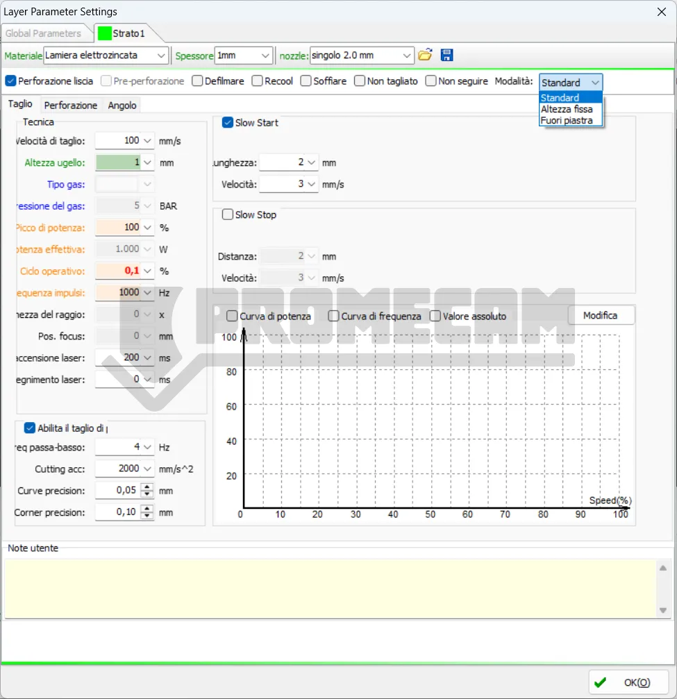
Clicking on “Layer” in the ‘Home’ menu opens the layer parameter settings window, which contains almost all the parameters related to processing. The “Layer” button is also located along the right edge of the screen in all views.
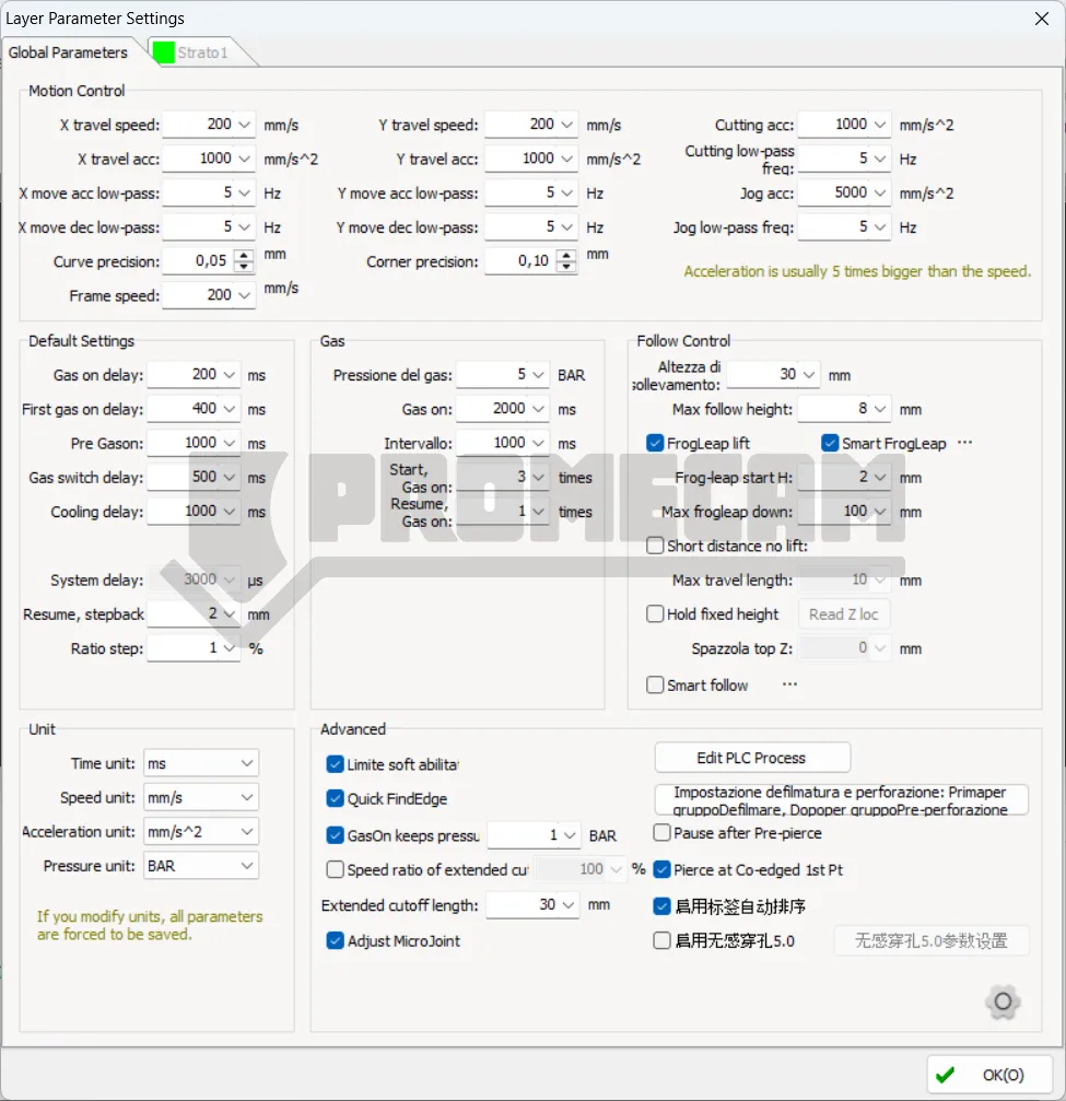
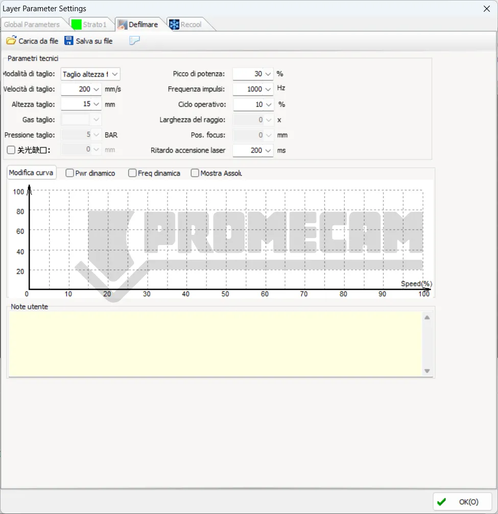
The first tab shows the “Global Parameters,” which serve as default settings common to the entire process. The other tabs list the applied layers, each of which can be configured individually. In the drop-down menus, you can enter the material, thickness, and nozzle used. Despite appearances, these are free text fields. At the bottom of the window, there is a Notes field where you can enter any comments. By clicking on the floppy disk icon in the upper right corner, you can save the cutting table. By clicking on the folder icon, you can apply the cutting settings contained in a previously saved table. This action will overwrite the settings currently in the layer, so if you don’t want to lose your parameters, be sure to save them to a file.
It is important to remember that parameter options may vary depending on the laser source, gas configuration, and height controller (capacitive sensor). The parameters shown in the images are for illustrative purposes only: users must set the values according to the actual conditions of the machine.
That said, let’s move on to describing and analyzing the main cutting parameters that can be set in the cutting tables.
This is undoubtedly the most important parameter, together with cutting power. The set value is to be considered theoretical, as it is the maximum speed at which the machine will cut. In reality, the average speed will be lower due to acceleration and deceleration ramps on corners, holes, etc. The balance between speed and power is very delicate: the higher the speed, the less time the laser beam deposits energy on a given point. Therefore, increasing the speed has an effect similar to a decrease in power. Conversely, a low speed results in more heat and greater melting of the material. Usually, decreasing the speed improves the quality of the cut, but going too slow is not a guarantee of a satisfactory result.
Set the distance between the nozzle and the sheet metal during cutting.
Set the type of auxiliary gas used for cutting. Oxygen usually has a separate inlet line, while air and nitrogen do not: this is because the two gases are functionally equivalent for the machine. We see the difference in terms of color and effect on stainless steel cutting.
Sets the pressure of the auxiliary gas during cutting; a proportional valve is required. Many machines from Asia do not have a proportional valve for nitrogen because the cost of gas in those countries is so low that the cost of the valve is unnecessary. In Europe, on the other hand, nitrogen is quite expensive (especially after recent price increases). For this reason, Promecam always installs a proportional valve for nitrogen.
Sets the maximum power of the fiber laser. The peak power determines the maximum cutting power that the machine can achieve. The energy is not delivered continuously, but in short, powerful “flashes” of light. The peak power is the measure of the intensity of each of these flashes.
For example, in a 3000 W cutting machine, if the peak power is set to 80%, the maximum power will be: 3000 W × 80% = 2400 W. Higher peak power allows the material to be vaporized more quickly and cleanly. This is essential for cutting thick or highly reflective materials, as it provides the energy needed to overcome their initial resistance in a very short time.
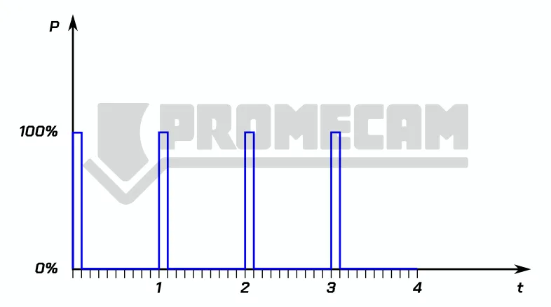
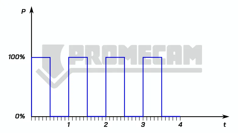
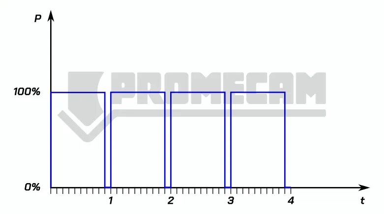
Sets the duty cycle of the PWM (pulse width modulation) signal used in machining. PWM (Pulse Width Modulation) is a way of controlling the average power of a signal by varying the duration of the pulses. Here are some visual examples to better understand the concept:
Here, the pulse is very short compared to the total period. This means that the average output is low.
The pulse is “on” for half the period and “off” for the other half. The average output is exactly half the peak power.
The pulse is almost always “on” for most of the period. This produces an average output close to the peak power.
Indicates the frequency of the PWM modulation signal, i.e., the number of laser pulses emitted per second, measured in Hertz (Hz). Changing this setting has a direct impact on the speed, quality, and heat-affected zone of the cut.
Increasing the PWM frequency in fiber laser cutting increases the number of pulses but reduces the energy per pulse, resulting in less localized heating and a cleaner, more precise cut, with potential color changes due to oxidation. Conversely, a lower frequency provides more energy per pulse, resulting in greater vaporization of the material, a rougher surface finish, and deeper cuts. Therefore, the frequency must be optimized for the specific material and desired result.
It defines the distance in mm between the focal point and the surface of the sheet metal. A zero focus means that the narrowest point of the beam is on the upper surface of the sheet metal. If the focus is below, i.e., inside the material, it is called negative. If, on the other hand, it is above the sheet metal, it is called positive. The position of the focus affects the width of the cut and the burr. As a rule of thumb, a zero focus is used for thin sheet metal. The positive and negative selection of the laser cut focus is not determined by the material of the cutting plate (stainless steel, carbon steel), but by the cutting method (oxidation cutting, fusion cutting). On thicker sheets of common steel cut with oxygen, a positive focus can be set. For cutting stainless steel or aluminum in air or nitrogen, a negative focus is recommended. Obviously, these are general principles; special materials such as brass or titanium may require opposite parameters.
Duration of the delay when the laser is switched on, to ensure that the material is completely pierced. After piercing, the gas and laser are kept active for this time before starting to move along the cut.
Delay applied before the laser is turned off to ensure completion of the cutting segment. Useful if there is a delay between the theoretical and actual positions of the servomotors.
After cutting, the laser switches off and gas is activated to cool the material.
This level will not be cut.
This level will be cut without height control via BCS100. The BCS100 automatic height control uses a capacitive sensor to measure distance and maintain a constant height even with deformed sheets. It works by detecting the electrical capacity between the sensor on the laser head and the material below. Since the capacity varies with distance, the system is able to calculate and adjust the height in real time.
The BCS100 uses a closed-loop control method, which means it continuously monitors the distance and sends signals to a servomotor to make immediate adjustments, ensuring millimeter precision. It is designed to work with laser cutting control software such as CypCut. This integration allows you to automate advanced functions, including:
Some of these settings are available in the “Global Parameters” tab, such as the “frog leap” function illustrated below.
Keeps the gas on during transitions between cutting paths.
Performs piercing at all starting points of the design or on primary lines before starting the cut.
The “Global Parameters” window contains the “Group Pre-piercing” option; when activated, the machine will pierce an entire group and complete the processing of that group before moving on to the next one. Note: “Pre-pierce” cannot be selected together with “Defilm.”
Removes the protective film along the design before starting the cut. After selecting this option, a tab dedicated to the “Defilm” layer will appear.
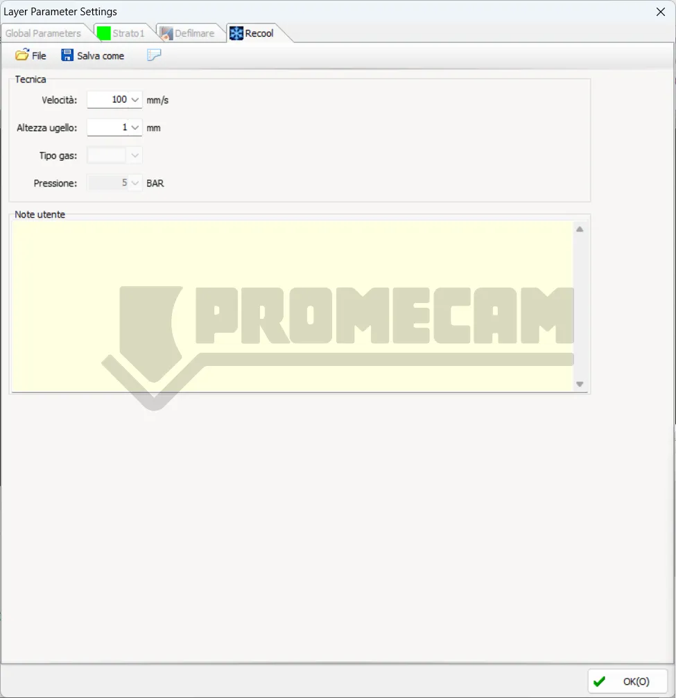
After completing a program, it turns off the laser and repeats the cutting path while keeping the gas active to cool the material and reduce the thermal effect on the precision of the piece. After selection, a tab dedicated to the “Recool” layer will be displayed. To avoid wasting gas, we recommend using compressed air.
These three modes can be selected from the drop-down menu at the top right of the “Layer” window.
Processing will follow the preset parameters.
The laser head will maintain a constant height throughout the entire cutting process.
By selecting this mode, the laser head will start cutting outside the sheet at a reference height and will switch to the cutting height as soon as it enters the sheet. This is useful when you want to cut a sheet in two, for example to separate the scrap from an intact part. To set the reference height, position the head at the desired height, then go to:
CNC > BCS100 > Save out-plate reference height to save the parameter.
Set the slow cutting distance after the contour start point.
Set the slow cutting speed for the start distance.
Set the slow cutting distance before the contour end point.
Set the slow cutting speed for the stop distance.
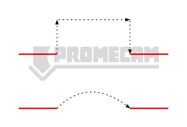
You can customize the power/frequency curve. The software will adjust the laser power (PWM signal duty cycle) and frequency in real time according to the curve, which is very useful for optimizing cutting quality in corners.
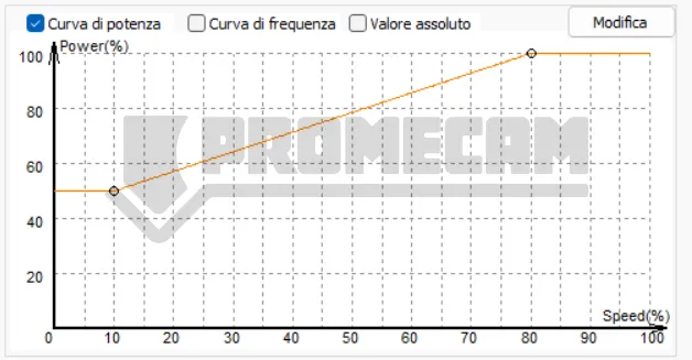
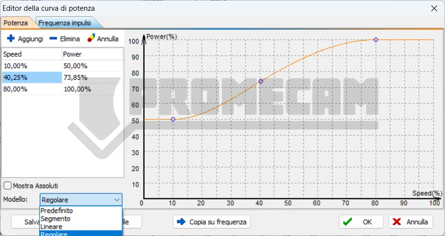
Note: The frequency curve cannot be selected individually.
When precision mode is enabled, you can set the low-pass frequency, cutting acceleration, curve precision, and angle precision for individual layers.
The lower the low-pass frequency value, the less impact there will be on the machine. The lower the curve precision and angle precision values, the greater the precision of the machining.
Smooth pierce is suitable for cutting thin and medium-thickness sheets, ensuring high efficiency and extending the life of the protective lens.
We recommend vibration suppression in automatic mode; the system will automatically perform suppression based on the technical cutting parameters.
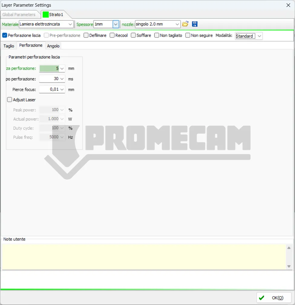
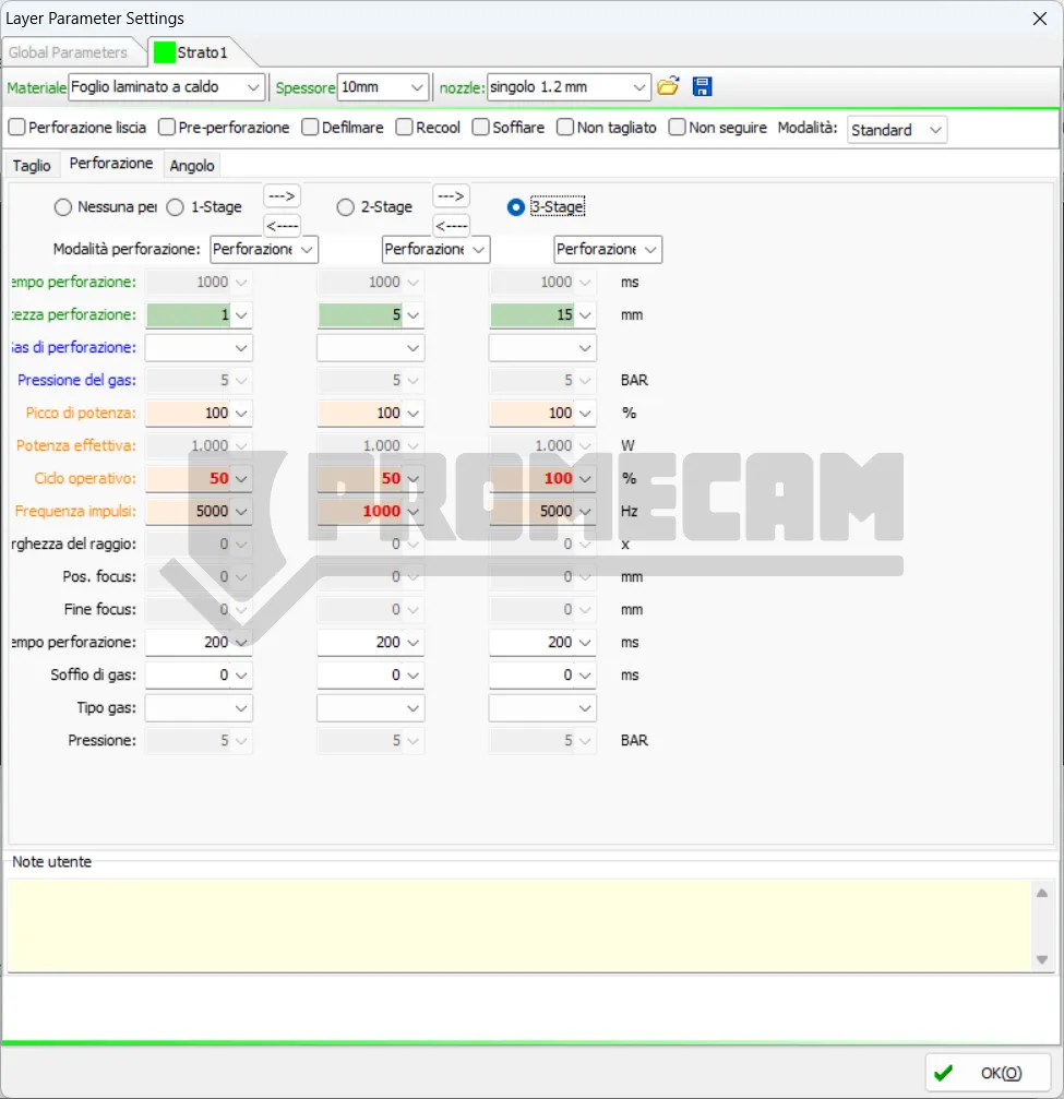
Piercing allows you to completely pierce the sheet metal at a predetermined point in the cutting path. In the case of materials that are very thick in relation to the power of the material, it is advisable to activate piercing in two or even three steps. Note that the phases are in descending order, with phase 1 being the last before the actual cut. So if we set piercing in three steps, the phases will be 3 > 2 > 1 > cut. The parameters for phase three will, for example, see a higher head position to avoid material splashing.
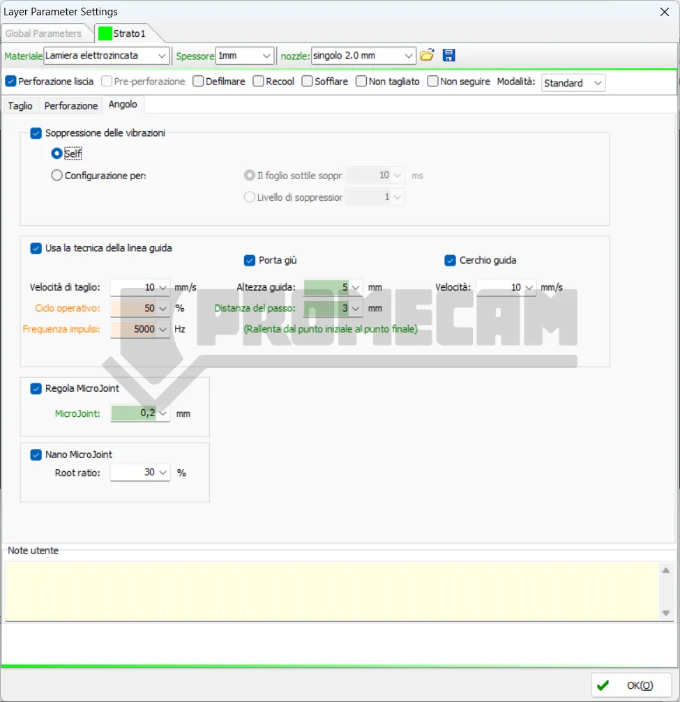
This function improves the quality of the cut on thicker materials or when the machine encounters excessive vibrations, especially during high-speed movements.
These parameters control the lead-in and/or lead-out line, i.e., the path that the laser takes to enter (and exit) the profile to be cut to ensure that the edge is clean.
Note: “Slow down from start point to end point” is an indication that the software can automatically handle deceleration/acceleration at the start and end of the guide line for a smooth transition.
MicroJoints (or Micro-Connections) are small uncut points that keep the cut piece attached to the scrap sheet (skeleton). This prevents the piece from falling and potentially hitting the laser head, as well as facilitating removal after cutting.

